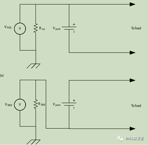
On systems with isolated power battery stacks, it is an important feature to detect isolation faults or ground faults (accidental current paths between power battery stacks and ground potentials or referenced components). Because the rest of the system may not be powered up if the battery is disconnected, it makes sense to put this function in the battery system. The most common methods for detecting and isolating faults will be described in detail below,
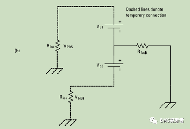
It is assumed that there is a resistance fault between the power battery system and the ground. This fault may occur at any potential of the battery system. Assuming that in general, the fault occurs between the two terminals of the battery, the battery pack is effectively divided into two subgroups, and the following equivalent circuit is generated. The insulation resistance value needs to be calculated twice. For each measurement, a known resistance is inserted between the positive and negative terminals of the battery and the grounding, and the voltage on this resistor is measured. This isolation measurement can be carried out regularly. Continuous isolation measurement is usually used to provide continuous monitoring of this important safety parameter. However, it is important to understand the timing limitations of this circuit. Consider the same circuit, but include the Y capacitance between the high voltage bus and the ground. When the measuring resistor Riso is inserted, it now uses y-capacitors to form an RC circuit. The capacitor must be fully charged before measurement. This specifies the minimum time required to perform this measurement and therefore the maximum frequency at which the measurement can be performed.


Isolation faults may occur due to conductive bridges between conductive parts formed on the circuit board, internal faults of isolation elements, insulation faults and other hazards. Isolation fault is dangerous to the staff of the battery system, and multiple distributed isolation faults with different potentials will cause short circuit hazard. Therefore, many applications specify that the operation of reducing the isolation resistance is prohibited, or the user must be warned at the same time. The battery management system itself is a place where high voltage and systems with different reference potentials are in close contact and may fail. Disconnection and battery can be isolated for detection to provide fault location. If there is an isolation fault outside the battery, opening the battery contactor will put the system into a safe state. If there is an isolation fault inside the battery, even if the contactor is open, there may be a dangerous situation.
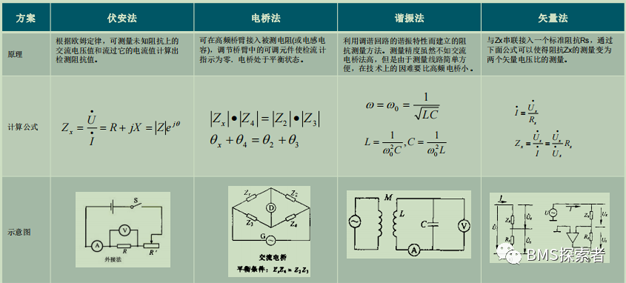
Common methods and characteristics of insulation resistance detection:
Voltammetry:It is simple and easy to measure and calculate. The resistance measurement has good real-time performance, but the voltage and current measurement are required to be synchronized.
Electric bridge method:The resistance measurement accuracy is high, but high-precision reference resistance and current measurement sensors are required.
Resonance method:It can be used to measure impedance components with inductive capacitance, and the cost of measuring resistive components is too high.
Vector method:The amplitude and phase of impedance can be measured accurately. But it is difficult to analyze the phase sensitive circuit.
Principles of common methods for insulation detection:

National standard method:
The improved volt ampere method is used to measure the insulation resistance, that is, the reference resistance is used in parallel, and the insulation resistance is obtained through simple mathematical operation. The advantage of the improved resistance measurement method is that the current sensor is eliminated; The problem of asynchronous sampling of voltage and current is avoided.


Disadvantages:
The calculated insulation value is low. Due to the parasitic equivalent capacitive reactance between the positive and negative poles of the system to the ground, the voltage between the positive and negative poles to the ground changes slowly during k1/k2 switching. If the sampling speed is too fast, the collected voltage value may not be stable and low, resulting in calculation error, and the calculated insulation value jumps. During the sampling process, the system operates under the dynamically changing current condition, and the voltage between the positive and negative electrodes to the ground will also change with the working condition, unstable, resulting in calculation error. When the insulation impedance itself is coupled with AC and DC during system operation, the system may undergo structural changes, resulting in calculation errors.


 Home
Home Products
 Telephone
 Message


